Troubleshooting
Fault Finding Procedure
Warning! It is a prohibited to work on a gas appliance unless you have proper qualifications (Gas Safe Registered). If there is an issue with your boiler and you need help contact customer service team immediately.
Things you need to remember before using the boiler, after each restart and repair
1.Before lighting the boiler you are advised to have a professionally qualified person check that the installation of the gas supply:
– perform all electricity (electrical) and gas operation
– your boiler is fitted with all the safety and control devices required by the current regulations.
– pressure relief valve is connected and terminated the way it allows necessary and safe discharge. Responsibility for damage caused by pressure relief valve opening and consequent water escape is not manufacturers!
2. On detecting the smell of gas:
– all electrical switches should be in off position, all electrical equipment should be switched off
– open the windows and doors so that the fresh air can come in and replace condensate gas
– turn off the gas clocks
– get the assistance Gas Safe registered service engineer
3. Do not touch the appliance with any parts of your body
4. Never hang or put anything next to or on a boiler itself.
5. All repairs, service and maintenance work (under or over guarantee) must be carried out only by an authorized boiler service engineer using Ideal original spare parts.
6. Your boiler will heat the water to temperature chosen by you, but it needs to be in a range up to 35 degrees from the source temperature
7. Boiler should be immediately switched off you you suspect that it is not working properly and Ideal service engineer or Gas Safe Registered engineer needs to be called.
Boiler reset
Warning! RESET will take all parameters back to the factory value. Reset is displayed by switch on of all symbols present on the display.
To reset the boiler hold reset button (E) for 10-15 sec. Button shown on a Control Panel with button descriptions below
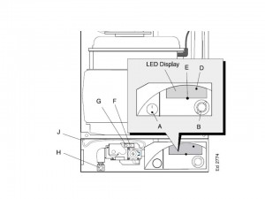
A- on/off button
B- Thermostat knob
D- Burner on neon
E -Reset
F- Injector pressure test point
G – Inlet pressure test point
H- Gas service clock
J- Casing pressure test point
Servicing your Appliance
Per users manual and safety reasons and efficient operation your boiler should be serviced once every year. Your boiler engineer will perform all necessary checks and some cleaning (igniters, burner,gas valve, pipes etc) and well as will check complete boiler functionality. It is your responsibility to make sure that proper ventilation is being provided at all times (no materials should be placed close to or over the boiler). Chimney ventilation checks are also your responsibility and should take place annually- prior boiler servicing. It set by law that any service work must be carried out by a Gas Safe Registered installer.
Error codes
The LCD display indications provide help in the diagnosis of fault finding.
All Ideal combination boilers are designed to heat up water directly from the main water supply at your home. Water goes through the boiler and it being heated up, produce goal is 35°C temperature rise in comparisment to water inlet temperature and between 35-85 degrees. Due to temperature variations between simmer and winter flow rates can be adjusted at the outlet taps to achieve the same temperature all year round. It is not associated as boiler fault.
We advice to you check through the following guide tables when identifying problems and for the purpose of correct communication with customer service representative or requesting a service engineers visit. In instances where the problem found be other than with the appliance Ideal service engineer will a charge for the visit if your boiler is out of warranty period.
Table A – general fault finding table for Ideal HE24, HE30, HE35 boilers
| Problem | Error | Solution |
| ‘L’ ‘F’ alternating | flame error | 1. Check gas supply and rectify fault
2. Replace PCB 3. Replace 4. Replace gas valve 5. Replace ignition electrode and associated harness as necessary |
| ‘L’ ‘E’ or ‘H’ ‘E’ alternating | board error | Replace PCB |
| ‘L’ ‘A’ alternating | overheat error | 1. Replace overheat thermostat
2. Fill and vent the system and open all isolation valves 3. Set CH control knob to maximum. If the overheat trips again measure the flow temp:Over 90 then Check control thermistor, if under 90r replace overheat ‘stat 4. Replace the system pump |
| ‘L’ ‘8’ alternating | fan error | 1. Replace fan
2. Replace PCB 3. Replace harness |
| ‘H’ ‘1’ alternating | flow thermistor error | 1. Replace the thermistor
2. Replace PCB 3. Check and replace wiring as necessary |
| ‘H’ ‘F’ alternating | short circut error | 1. Replace PCB |
| H’ ‘4’ alternating | flue thermisor error | 1. Fill and vent the system and open all isolating valves
2. Inspect heat exchanger for blockage or damage in the flueways.Clean or replace as necessary 3. Replace thermistor |
| H’ ‘n’ alternating | phase reversal error | 1.Check wiring to the boiler for reversed live and neutral |
Table B- fault finding table Ideal Icos models
| Problem | Solution |
| Boiler is not working for central heating or hot water. | 1.Check there is power to the boiler ñ switch (A) in the ON position and 0 displayed on the controls. If “0”is not displayed then not a boiler fault contact your installer/service company.
2. Check external programmer is set to an ON period and the relevant function selected i.e. central heating or domestic hot water. Test by overriding the programmer by setting to continuous. 3. Check room thermostat for central heating or the cylinder thermostat for domestic hot water, are set at the required temperature. To test operation of either thermostat turn fully up. If no response contact your installer. |
| Boiler is not working for central heating or hot water but attempts to fire by going through 3 ignition attempts. Display shows ‘L : F ’ (flashing). | 1. Press reset button (C) for 2 seconds to repeat ignition sequence.
2. Check gas supply (try another appliance cooker/fire etc.) If no gas supply then not a boiler fault contact gas supplier. 3.Check condensate pipe is not blocked or frozen. If blocked, clear blockage, if not possible to check contact your installer. |
| Boiler is not working for central heating or hot water and the display shows ‘L:A ’(flashing). |
1. Press reset button (C) for 2 seconds, the boiler should then re-light. If fault recurs this indicates an overheat condition. The boiler should be turned off and your installer contacted.
2.Check if ALL radiators have thermostatic radiator valves fitted. If they have contact your installer. |
Table C – fault finding table Ideal Mexico Heating boilers
| Problem | Solution |
| Boiler is not working for central heating or hot water. | 1.Check there is power to the boiler – switch (A) in the ON position and ‘0 ’ displayed on the controls.
2.If ‘0 ’ not displayed then not a boiler fault – contact your installer/service company. |
| Boiler is not working for central heating or hot water but attempts to fire by going through 3 ignition attempts. Display shows ‘L : F ’ (flashing). | 1.Press reset button (D) for 2 seconds to repeat ignition sequence.
2.Check gas supply (try another appliance – cooker/fire etc.) – If no gas supply then not a boiler 3.Check condensate pipe is not blocked or frozen. If blocked clear blockage – if not possible to check contact your installer. |
| Boiler is not working for central heating or hot water and the display shows ‘L:A ’(flashing). |
1.Press reset button (D) for 2 seconds, the boiler should then re-light. If fault recurs this indicates an overheat condition. The boiler should be turned off and your installer contacted.
2. Check if ALL radiators have thermostatic radiator valves fitted. If they have contact your installer. |
| Boiler is not working for central heating or hot water and the display shows ‘H:A ’(flashing). | 1.Check pressure gauge on boiler shows a minimum of 1 bar. If not re-pressurise via the filling loop to 1 bar (if unsure contact your installer), turn off the tap on the filling loop and turn the on/off switch (A) off and then back on again to reset the boiler. If unable to do so or if the pressure continues to drop after filling then contact your installer.
2.Check if ALL radiators have thermostatic radiator valves fitted. If they have contact your installer. |
| Boiler will not fire for central heating. | 1.Check external programmer is set to an ‘ON’ period. 2.If already set to an ‘ON’ period then check the programmer by setting to continuous if boiler then fires – Contact your installer to rectify the programmer.3.Check room thermostat by turning fully up, If ‘0’ is not displayed on the user controls then contact your installer. |
| Boiler comes on for domestic hot water without atap being opened – the display shows ‘D’. | 1. Check for dripping / dribbling taps or showers – turn fully off.
2.Check for leaks from the domestic hot water pipework and if found contact your installer. |
| Boiler fires occasionally for approx. 2 minutes – the display shows ‘t’. | 1. This is a normal function of the boiler to periodically pre heat the plate heat exchanger to optimise delivery time for domestic hot water to taps or showers. |
Repair and replacement parts
To arrange annual service, repair or parts replacement contact Ideal customer service specialists by explaining what is being requested- annual service or repair. Ideal boiler specialist will come with some spare parts from same manufacturer as the original complete boiler to assure the quality and safety. Two years guarantee is provided for all the spares.
Initial steps
- Before you start to work on Ideal boilers turn off the thermostat knob and wait till boiler cools down
- Always isolate the electricity supply
- Turn off the gas at both : the gas valve and at the gas meter
- Each time when removing any items containing water (hoses, pipes etc) make sure they do not spill on electrical components
- Each time conduct all electrical check: resistance, polarity and continuity before and after any work
Warning! Always test for gas soundness after completing any exchange of gas carrying components and carry out functional checks of controls.
Replacement of any component will require outer case front panel first. In order to do so follow the steps below
1. Isolate the appliance
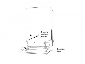
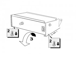
2. Open the controls pod door and release the 2 captive screws at the bottom of the casing. Swing the bottom of the boiler casing out until the controls pod casing has cleared the controls, then unhook the casing top from the pack panel.
Retain the casing in a safe place.
3. Re-assemble in reverse order
Fan and the Air box replacement
1. Isolate the appliance
2. Gain General Access -remove outer case front panel
3. Remove the 2 silicon rubber tubes from the fan sensing points.Disconnect the fan leads.
4. Rear flue. Slacken the M4 screw securing the flue connector to the fan. Disconnect the connector from the fan and slide into the flue.
5. Side or top flue. Loosen two M4 screws securing the flue elbow and flue connector. Disconnect the flue connector from the elbow and slide into the flue. Remove the flue elbow.
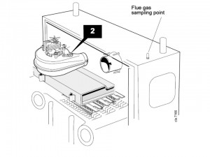
6. Disconnect the silicon rubber tube from the rear of the collector hood. Remove the two M5 nuts located on the front tie rods. This way you release the combustion chamber from the tie rods.
7. Loosen the central M5 fixing screw. It is located at the collector hood. Remove collector hood itself ( fan disassembly).
8. Loosen the three M4 screws. Keep the fan for the collector hood.
9. Re-assemble in reverse order
Warning! Before reassembling ensure the fan gasket is correctly mounted. After any service operation on the components of the gas circuit check all the connections for gas leaks.
Ignition electrode and lead replacement
1. Isolate the appliance
2. Gain General Access -remove outer case front panel
3. Remove the burner and air box assembly
4. Remove the electrode retaining nut
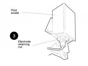
5. Remove the pilot shield
6. Remove the ignition electrode and integral lead
7. Refit the new electrode and lead in reverse order.Ensure that the pilot shield is replaced. Check the spark gap.
8.. Re-assemble in reverse order
Heat exchanger replacement
1. Isolate the appliance
2. Gain General Access -remove outer case front panel
3. Remove the burner / air box assembly
4. Drain the system.
5. Disconnect the water connections. If compression fittings are used then cut the pipes both above and below the fittings in order to allow the heat exchanger assembly to be removed. Remove the heat exchanger drain plug and drain the residual water into a suitable receptacle.
6. Remove the fan / collector hood assembly.
7. Remove the combustion chamber by unscrewing the 4 tie rods.
8. Remove the thermostat sensors from the pockets on the heat exchanger by removing the M3 screws and plates.
9. Slacken 3 turns only the 4 heat exchanger / interpanel retaining screws.
10. Lift the heat exchanger / interpanel assembly upward and forward to disengage key hole fixings. Pull the assembly downwards to clear the water pipes from the back panel.
11. Remove the 2 rubber sealing grommets from the top of the back panel to facilitate fitting the new assembly.
12. Fit the new heat exchanger assembly, complete with water pipes, and hang it on the key hole slots and screws. Retighten the screws.
13. Replace the 2 rubber sealing grommets.
14. Re-assemble in reverse order in reverse order.
Warning! Remake all water connections, ensuring that the compression fittings (if used) are correctly refitted. Fully test all functions, including water and gas soundness.
Pilot Burner replacement
1. Isolate the appliance
2. Gain General Access -remove outer case front panel
3. Remove the burner and air box assembly.
4. Remove the electrode retaining nut and remove the pilot shield and electrode.
5. Loosen screws fixing central pilot and lift the pilot clear of the pilot injector. Now you can unscrew the pilot injector itself
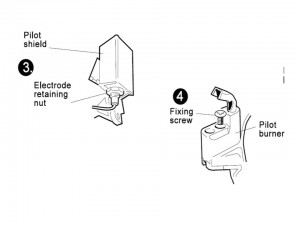
6. Place the new pilot burner and new injector. Put the M4 screws aside. Ensure the copper sealing washer is replaced when refitting the pilot injector.
7. Replace the pilot shield and the electrode, put aside nut and electrode. Check the spark gap.
8. Re-assemble in reverse order. The pilot is factory set to maximum and no further adjustment is possible. Ensure there is an inlet pressure of 20 mbar available. Also check burner ignition and cross-lighting.
Main Burner replacement
1. Isolate the appliance
2. Gain General Access -remove outer case front panel
3. Remove screws holding the front burner and its supportive strap.
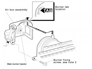
4. Loosen the M5 pozition screw, you will find it on the left hand bottom side of the burner. Pull the burner towards down and loosen the retention tab. You can now remove the burner.
5. Remove burner, check/clean or replac as required. Ensure that a new copper sealing washer is used.
6. Fit the new burner, ensuring that the retention tab is correctly located in the airbox slot
7. Re-assemble in reverse order. Check the burner for cross-lighting and flame stability.
Overheat Thermostat replacement
1. Isolate the appliance
2. Gain General Access -remove outer case front panel
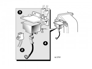
3. Remove the control box fixing screws.
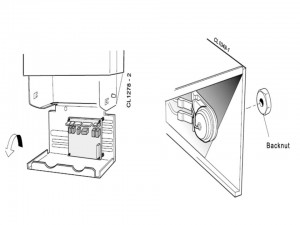
4. Swing the control box down into the servicing position as shown on the picture below
5. Pull off the electrical connections at the thermostat. Remove the backnut retaining the thermostat to the bracket. Withdraw the thermostat phial from the heat exchanger pocket as described on the picture below
6. Fit the new thermostat
7. Re-assemble in reverse order.
8. Apply an adequate quantity of heat conducting compound between the condensing heat exchanger and the thermostat.
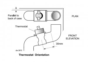
Overheat Thermostat replacement
1. Isolate the appliance
2. Gain General Access -remove outer case front panel
3. Remove the limit thermostat assembly from the boiler flow pipe as shown on the picture below
4. Disconnect the electrical connectors
5. Re-assemble in reverse order. Pay special attention to correctly position the limit thermostat as shown in the orientation diagram.
Spark generator replacement
1. Isolate the appliance
2. Gain General Access -remove outer case front panel
3. Disconnect the leads from the spark generator and bracket
4. Remove the M4 screw securing the spark generator bracket to the flue casting
5. Remove the 2 M4 screws securing the spark generator to the bracket
6. Fit the new spark generator
5. Re-assemble in reverse order.
Air pressure switch (APS) replacement
1. Isolate the appliance
2. Gain General Access -remove outer case front panel
3. Remove the APS fixing screw.
4. Remove both sensing tubes from the APS.
5. Remove the 3 electrical connections from the APS. Fit the new APS
6. Re-assemble in reverse order
Warning! After cleaning or replacement as detailed above, if it deemed necessary to undertake a combustion analysis.
Detection electrode replacement
1. Isolate the appliance
2. Gain General Access -remove outer case front panel
3. Pull the electrode and lead from the PCB connection
4. Remove the bracket retaining screw
5. Pull the bracket forward to disengage the rear retaining clip.
6. Remove the bracket.
7. Remove the screw retaining the detection electrode.
8. Fit new detection electrode
9. Re-assemble in reverse order.
Control PCB replacement
1. Isolate the appliance
2. Gain General Access -remove outer case front panel
3. Swing the control box down into the servicing position. Disconnect the detection lead from the PCB.
4. Unplug all the Molex connectors from the PCB. Disengage the PCB from the mounting posts and withdraw from the control box.
5. Fit the new PCB
6. Re-assemble in reverse order.
Warning! After cleaning or replacement as detailed above, if it deemed necessary to undertake a combustion analysis.
Casing seal replacement
1. Isolate the appliance
2. Gain General Access -remove outer case front panel
3. Remove the old seal from the casing surround and thoroughly clean the casing surfaces
4. Fit the new adhesive seals.
5. Replace the boiler casing.
Control Gas valve replacement
1. Isolate the appliance
2. Gain General Access -remove outer case front panel
3. Remove the burner and air box assembly
4. Remove the fixing screws. Swing the control box down into the servicing position
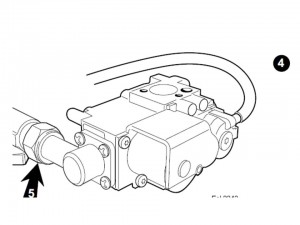
5. Disconnect the gas control valve electrical leads.Undo the gas cock union
6. Whilst supporting the gas control valve, remove the 2 screws retaining the manifold to the back panel.
7. Remove the gas control / manifold assembly. Remove the 4 screws retaining the manifold to the gas control valve, and fit the manifold to the new valve. Ensure that the new control is fitted the correct way round (an arrow engraved on back indicates the direction of flow).
8. Transfer the gas cock union to the new gas control valve, using an approved jointing compound.
9. Re-assemble in reverse order.
Warning! After cleaning or replacement as detailed above, it is deemed necessary to undertake a combustion analysis
Programmer replacement
1. Isolate the appliance
2. Gain General Access -remove outer case front panel
3. Remove the fixing screws and swing the control box down into the servicing position
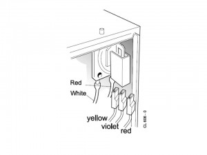
4. Pull off the terminal connections from back of programmer as shown on the picture below
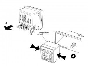
5. Compress the lugs at each side of the programmer and withdraw it from the control panel. Fit the new programmer.
6. Re-assemble in reverse order. Set the programmer to the desired program and check the operation of the boiler.
Sightglass replacement
1. Isolate the appliance
2. Gain General Access -remove outer case front panel
3. Unfasten the 2 nuts and washers holding the sightglass assembly to the casing front panel as described on the picture below
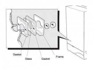
4. When fixing the new assembly, ensure that the parts are in the correct order. The frame must have the return edge at the bottom.
5. Re-tighten the 2 nuts to ensure an airtight seal. Do not over-tighten.
6. Re-assemble in reverse order
Mains switch replacement
1. Isolate the appliance
2. Gain General Access -remove outer case front panel
3.Remove the 2 control box screws and lower the control box. Push out the mains switch from the rear, as shown on the picture below
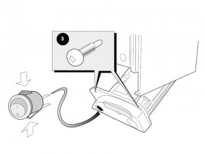
4. Refit the new switch, ensuring that the electrical leads are replaced on the correct terminals and the key on the switch is correctly aligned with the slot in the plastic moulding.
5. Re-assemble in reverse order
Condensate trap replacement replacement
1. Isolate the appliance
2. Gain General Access -remove outer case front panel
3. Undo the plastic union nut on the condensate ‘S’ trap outlet. Remove the 2 screws. Pull the trap down and forward to remove.
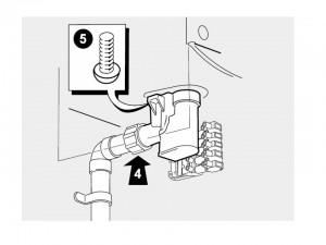
6. Re-assemble in reverse order. Ensuring that the new trap is full of water.
Combustion chamber insulation replacement
1. Isolate the appliance
2. Gain General Access -remove outer case front panel
3. Remove the burner and air box assembly. Remove the 4 tie rods. Remove the combustion chamber. Remove the 2 side panel retaining brackets. Remove the side insulation panels. Remove the front and rear insulation panels.
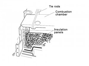
4. Fit the new front and rear insulation panels.
5. Fit the new side panels and retain with the brackets and screws previously removed.
6. Re-assemble in reverse order
Flueways cleaning
1. Isolate the appliance
2. Gain General Access -remove outer case front panel
3. Remove the collector hood by undoing the front tie rodnuts. The tie rods should be released from the combustion chamber.
4. Loosen four collector hoods as described on the picture below. Keep screws and washers
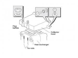
5. Uncouple and loosen the flue baffles on the heat exchanger.
6. All loose deposits should be removed from the heat exchanger. Put special attention to space between the fins. You can use the suitable brush.
6. Re-assemble in reverse order
Burner cleaning and pilot assembly
1. Isolate the appliance
2. Gain General Access -remove outer case front panel
3. Remove any dust that is located on the burner head and ensure that the flame ports are free. Warning! Metallic bristles brushes shouldn’t be used.
4. Ensure there is no blockage by removing the main burner injector. Clean or replace if necessary.
5. Refit the injector, using an approved jointing compound sparingly. Inspect the pilot burner and ignition / detection electrode. Ensure that they are clean and in good condition.
6. Check if: the pilot burner injector isn’t damaged, the pilot burner is clean and unobstructed, the ignition / detection electrode is clean and undamaged, the ignition / detection lead is in good condition, the spark gap is correct . Clean or renew as necessary.
Ventilation
The ventilation requirements in the gas fired boiler standard are also valid for oil fired boilers of the same heat input. The ventilation requirements of Idal boilers depend from the flue used in the system, and their heat input. All ventilation points must be permanent with no means of closing. Those should be positioned to avoid accidental obstruction by blocking or flooding.
Warning! Boilers installed in or close to rooms in which the atmosphere is polluted with chlorine or fluorine compounds may be subject to high corrosion. This is an often case in hairdressing salons, places where there is a lot of cooling equipment. Boiler that are being installed in such locations are not be covered by the standard warranty.
Minimum clearances
A clearance of 450mm (17 3/4″) MUST be available at the front of the boiler for servicing.The minimum clearances given below must be kept in order to maintain the safe running of the boiler
- above the boiler 100 mm (4″)
- at each side of the boiler 5 mm (1/4″)
- under the boiler 100 mm (4″)
- in front of the boiler 5 mm (1/4″)
Cleaning
For everyday cleaning simply use a dry cloth. No special material needed. To remove difficult marks and stains, use a wet cloth first and then and finish with a dry cloth.
Frost Protection
If no frost protection is provided and frost is likely during a short absence from home, leave the heating controls at a lower than usual setting. However in situation when you won’t be using heating for whole season we recommend to drain the entire system. . In the cases when heating system includes a frost thermostat your boiler should be switched OFF only when you are not using it especially during the winter. The main water supply should be turned ON, and the boiler thermostat should operate in usual position.
Condense drain
The condensate drain should never be blocked or changed. Blockage by debris or freezing will result in automatic boiler shutdown. Whenever you suspect that pipe is frozen it is adviced to check by pouring hot water on the pipe you suspect is frozen, that will release the frozen water blockage from the end of the pipe. If however fault still occurs contacta Gas Safe Registered installer or Ideal customer service representative
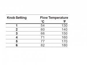
Water temperature control
Adjust the boiler thermostat to give the required temperature of central heating. Boiler has the function of automatically switching on/off the main burner in order to sustain pre-programmed temperature.
Approximate flow temperatures for the boiler thermostat settings are:
In an Emergency
The moment you suspect water or gas leak you should immediately switch off electrical supply in the house/apartment, next switch off the selector switch on the facia panel. Let fresh air to the house. Once you don’t feel gas in the apartment you can switch on the electrical supply back. For safety reasons gas supply should be switched off, you can do it either at the isolating valve or the meter itself . Call your customer support immediately inform about situation as detail as possible and request service boiler engineer as soon as possible.